


Your comprehensive guide to specifying and installing Safe-Life Toilet Alarms, Overdoor Lights, and its wide range of Optional Facilities.
Introduction: Toilet Alarm Systems for Safety & Compliance

Safe-Life Toilet Alarm Kits are designed to provide instant emergency assistance in bathrooms and disabled toilets. Ideal for schools, aged care facilities, hospitals, clinics, medical centres and public restrooms, these systems ensure help is always accessible.
The basic kit includes:
- A Safe-Life Call-Point with backlit [Call] button
- 12V Plug-Pack power supply [or]
- Alternative UPS 12v plug-pack with up to 12-hour battery back-up
- Overdoor light with integrated piezo sounder.
See attached Diagram 1
Optional enhancements are available for improved large installations and for safety and accessibility as below: –
- Mushroom Head (twist to release) slave call-points
- Multiple call-points and multiple overdoor light/buzzer assemblies
- Multiple toilet (or other) locations
- Remote (Admin) light/buzzer facilities
- Connection to security & building management systems
- Connection of alerting light or light and sound Strobes
- Call-point level connection of UHF wireless modules [or]
- Area level wireless module connection
- Connection of LED colour Alphanumeric Annunciators
- Connection of Alphanumeric Pagers
See attached Diagrams 2 & 3
How the Basic System Works: Call, Assist, and Cancel
- Call – Press the silicon [Call] button (Braille-marked and anti-bacterial).
- The call-point beeps and the LED flashes once as a reassurance.
- Connected overdoor light + buzzer assemblies continue to flash/buzz until call cancelled
- Assist – An attending carer can press [Call] + [Cancel] simultaneously to identify that Assistance is required.
- Cancel – Press [Cancel] button to terminate alarms on the call-point and all connected overdoor lights.
Coverage: Call-points can connect by cable to overdoor lights up to 400 meters away.
Key Features & Options
1. Call Button Customization
- Colours: Green [Call] (default), Red [Emergency], Yellow [Assist]
- Ensure the correct option is specified at purchase.
2. Mushroom Head Slave Call Point
- Mechanical Press-to-Latch, Twist-to-Release
- Ideal for toilet locations as an extension to a main call-point
- Must connect to a Master call-point or similar local control unit
3. Special UPS 12V Plug-Pack
- Provides up to 12 hours backup during power outages
4. Cord Pendant Connection
- Hygienic cord for disabled persons, clinics, or recovery beds
- Connects via a 6.5mm socket on a master call-point
5. Overdoor Light/Buzzer Options
- Superbright LED: Yellow (default) or Red
- Multiple light/buzzers recommended (e.g., outside the toilet, at reception)
6. Enclosures & Waterproofing
- Surface mount enclosures for tiled walls are available
- Waterproof gaskets for IP63 splashproof protection are available
7. Strobe or Relay Connection
- 12V output to trigger strobes or external alarms during a call
8. Building Management & Security Integration
- Momentary contact closure triggers external systems (security, fire, BMS)
9. Wireless Module Upgrade
- UHF wireless modules convert system from wired to wireless
- Supports alphanumeric Pagers and LED + Tone Annunciators
- Ideal for schools, clinics, and aged care facilities
Installation Guidelines
- Pre-wired call-point and overdoor light(s) for quick installation
- Flush or surface mounting options available
- Ensure cable lengths do not exceed 400 meters
- Optional modules (UPS, pendants, wireless) should be installed as per included diagram
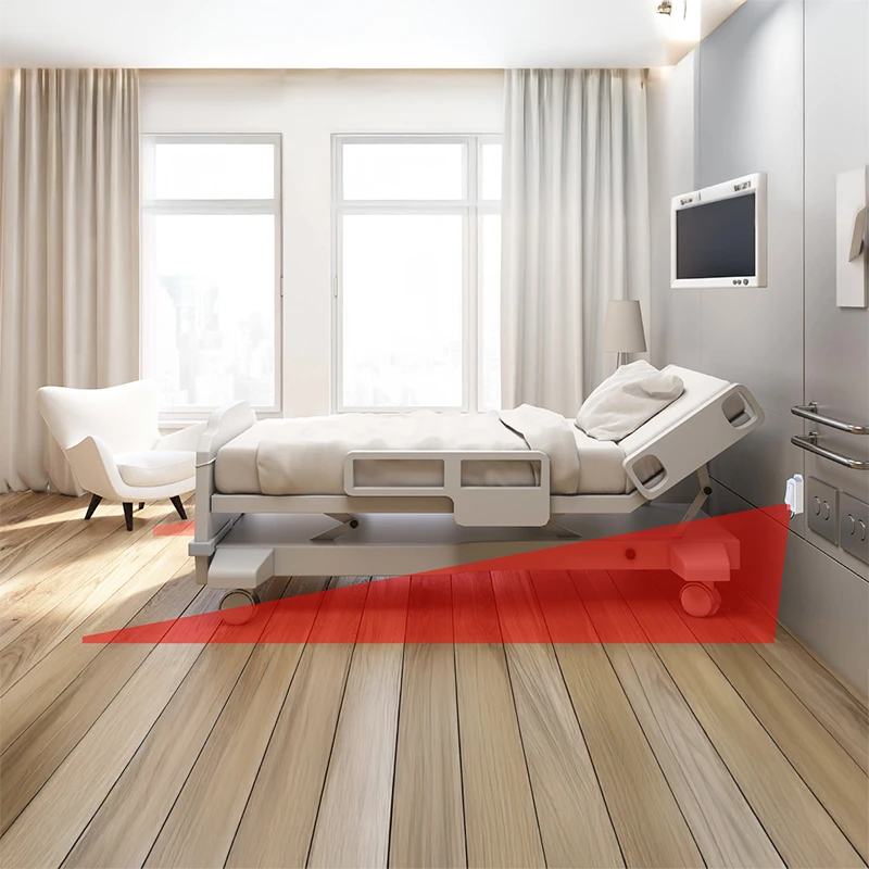
Recommended Applications
- Disabled toilets – Schools, shopping centres, hospitals
- Sick bays & recovery rooms – Clinics, schools and medical facilities
- Aged care & assisted living – For staff reassurance and resident safety
- Public restrooms – Compliance with local safety regulations
Maintenance & Troubleshooting
- Test call-point and overdoor lights regularly
- Replace batteries in UPS plug-pack annually
- Clean silicone buttons with mild disinfectant
- Check wiring and connections for signs of wear
Conclusion
“Safe-Life Toilet Alarm Kits are installed across Australia in Clinics, Medical Centres, private hospitals, universities, schools, and aged care facilities to ensure disabled toilet safety compliance.” They have proved reliable, customizable, and compliant with accessibility standards, offering peace of mind in every facility.
DIAGRAM 1 – Single Toilet

DIAGRAM 2 – Multiple Toilets

DIAGRAM 3 – Wireless Version

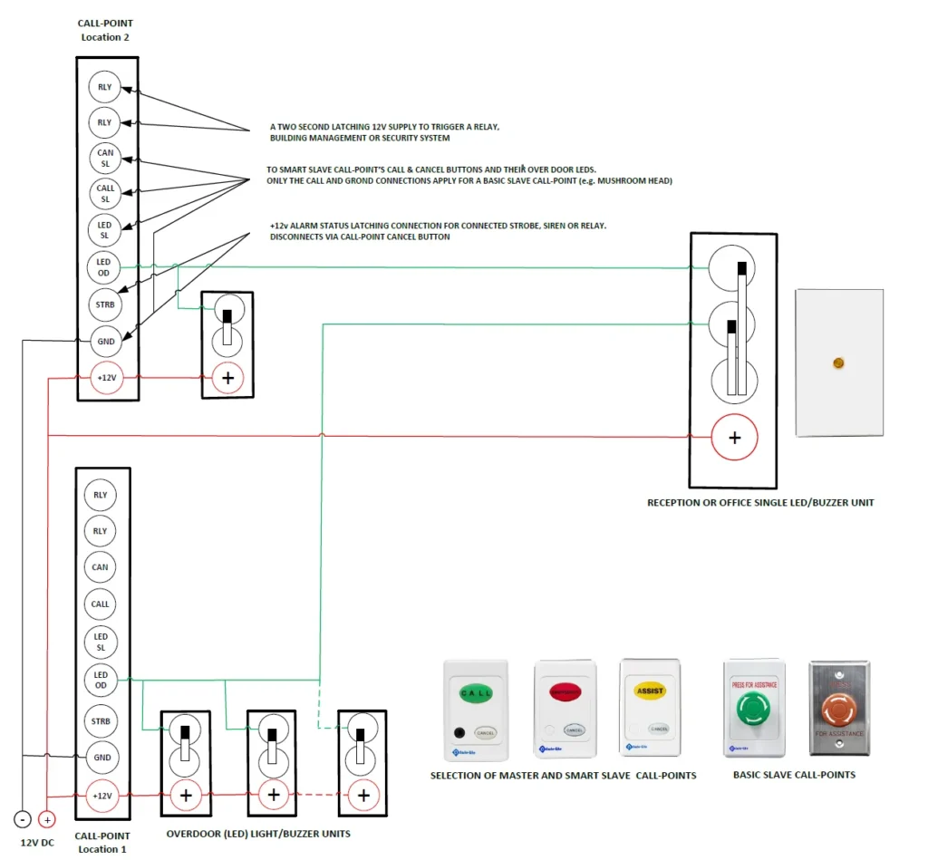
Diagram 4 – Multi-Toilet Hard-Wired Emergency Call Wiring Diagram – Two Call Locations, Multiple Over-Door Units, and Central Office LED/Buzzer Expansion
MULTI-TOILET HARD-WIRED EMERGENCY CALL-SYSTEM WIRING DIAGRAM SHOWING TWO SEPARATE LOCATIONS ONE HAVING UP TO 3 OVER-DOOR LIGHT/BUZZER UNITS WITH ALARM CONDTIONS FROM BOTH LOCATIONS EXTENDED TO A DISTANT CENTRAL OFFICE LED LIGHT/BUZZER UNIT.
NOTE. To include Pager and/or Annunciator displays a UHF wireless transmitter will be required at each location.
CALL-POINT DIP SWITCH SETTINGS
1. ASSIST – Normally off. [ON] will cause “fast cadence” LED flash rate. (This disables the normal two-button “Assist” function.
2. PIEZO – Normally on. [OFF] will silence the call-point Piezo. (It has no effect on overdoor or remotely connected Piezo buzzers).
3. TWIST – Normally off. [ON] for the connection of a “Twist Release mushroom head” (Slave) call-point.
4. MIRROR Normally off. [OFF] is only used when an LED fitted slave call-point needs to mirror LED functions.
